Design, analysis and additive manufacturing of print in place compliant suspension system.
Background of project
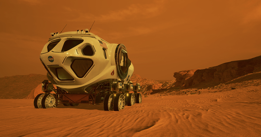
For more than a century, the products humanity has design have been constrained by conventional manufacturing practices like machining, moulding and casting. Additive manufacturing fundamentally changes that by directly integrating the design process with on-demand manufacturing without any topological constraints. Additive manufacturing when complemented with compliant mechanisms has the potential to drastically change the way by which products are designed and manufactured. A “Martian home on wheels” designed by NASA has been planned as a mobility solution on mars. Considering similar function and by using new techniques for design and manufacturing such as additive manufacturing and compliant mechanisms, this invention attempts to redesign the conventional suspension system specifically for extra-terrestrial applications.
Summary of the project
Cost of sending 1kg of payload to Mars is around 2.78 million USD/kg. Even if several efforts are made to reduce the weight of the payload still the carrying capacity for the payload is constrained due to the volume of the payload.
As humans are on the road to make humanity multi-planetary, various innovations are in the making to help mankind to start a civilization on Mars. In order to make an economic sense of this mission, there is a need to reduce the logistical cost to send required goods on mars which can only be achieved either by reusing the rockets which ferries the payload to and from mars or optimizing the payload by reducing its weight.
Transportation on the Martian surface is a major concern of the space industry as its nature of high complexity considering weight and volumetric constraints.
To reduce the number of individual components needed to land on the surface, this project addresses this problem by utilizing compacted earthly materials or local Martian materials and leveraging the advances made in Additive Manufacturing and Compliant mechanisms to make a uni-body printed in place suspension system. This project will reduce the payload logistics cost of the mission and will also reduce the complexity of the subsystem by reducing the number of parts required to build the system to one and provide flexibility to the designer to build systems which can negotiate a variety of technical terrains present on Martian surface.
Objectives:-
The objective of this project is to:-
- Develop a design methodology for Additive Manufacturing of compliant suspension systems.
- Develop a design validation plan for the same using analytical and practical methods.
- Develop a methodology to optimize or predict the fatigue failure characteristics of the mechanism.
- 3d printing of designed suspension system by selection of appropriate materials and slicing settings for strength and print time optimization.
Design methodology
Design of testing rig and payload:-
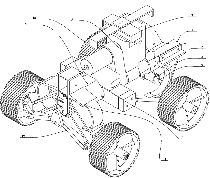
Design of a suspension system demands its sprung mass specification. A modular test rig on which propulsion system and proposed suspension system will be conveniently mounted and dismounted. A body chassis configuration of a conventional automobile can be compared with the proposed test rig once the test rig is built its sprung can be measured for further calculations. Design validation mechanism is also mounted on the testing rig.
Kinetics:-
Similar to a conventional suspension system, after arriving at a suitable ride rate for the terrain, required spring stiffness can be calculated. For kinetics calculation, weight of the sprung-mass was measured. The measured weight was considered as a force to calculate ride stiffness after considering suitable chassis sag height after the application of load.
Calculations:-
Weight measured (w) =~ 2000 g
Sag height (hs1) = 2 mm
Ride stiffness = W/hs1 = 2000/2= 1000 g/mm
Defining a proper ride stiffness is crucial as it dictates the vehicle suspension damping characteristics. Higher the sag height, softer the suspension system will react to the ground irregularities.
Further, the load is divided between all four wheels of the test rig, so considering weight distribution of 50:50 and the vehicle is loaded equally along both sides of the y-axis, dividing the ride stiffness by 4 to obtain wheel stiffness.
1000/4 =250 g/mm.
Which means on the application of 250 g of load on the suspension the wheel must travel by 1mm.
Material selection:
For all structural members, PLA was selected based on its strength, cost and availability.
For suspension modules, considering fatigue Performance, impact strength and bending and tensile strength, PETG [Polyethylene Terephthalate Glycol] was selected.
Design of flexure hinge:-
In order to achieve print in place method of manufacturing flexure hinges were selected over traditional ball joints. Flexure hinge when used upon eliminating ball joints are capable to dampen bump forces and improving NVH characteristics of the test rig. Usage of flexure hinge is also beneficial in the project’s use case as it reduces the number of individual parts in an assembly.
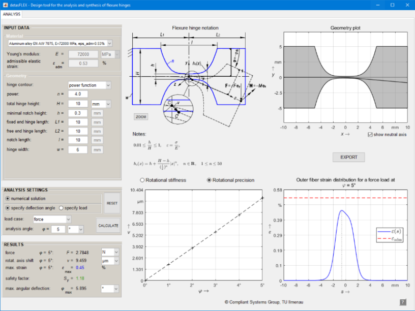
Detasflex is a program developed with MATLAB for the non-linear and contour dependent calculations of elastic and kinematic properties of notch flexure by solving a system of differential equations. Developed in 2018, this program specially focuses on synthesis of circular, corner filleted, elliptical and power function based flexure hinges.
Design of compliant spring:-
After synthesis of the proposed compliant suspension mechanism, Cumulative vertical stiffness produced through deflection of the mechanism can’t be sufficient to achieve initial ride rate for the proposed payload. In order to compensate for the remaining stiffness a supporting spring has to be incorporated.
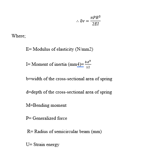
CASTIGLIANO’S THEOREM:-
Castigliano’s theorem states that when force δFi acts on elastic system subject to small displacement δi corresponding to the force, in the direction of the force, is equal to the partial derivative of the total strain energy δU with respect to that force. after solving:
Initial iterations
Based on these equations several iterations were designed. few examples are mentioned below
Final iteration
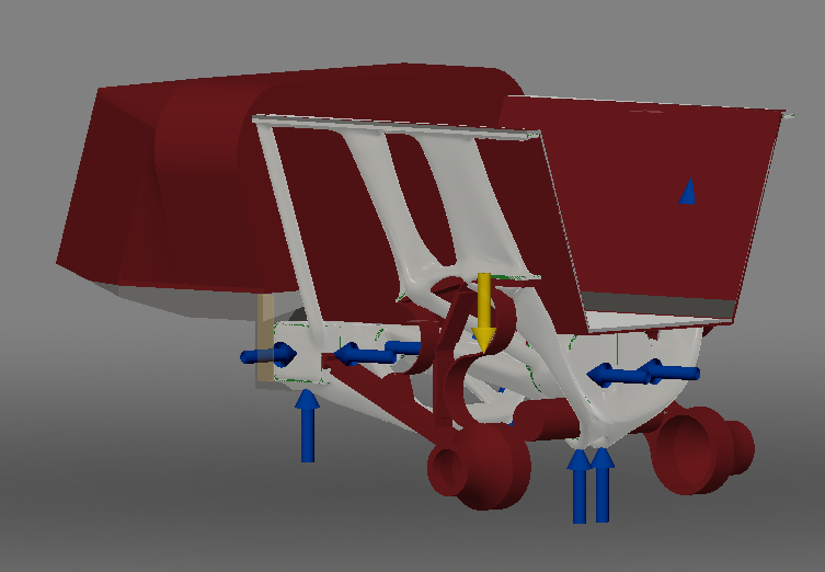
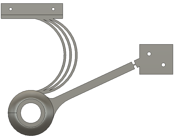
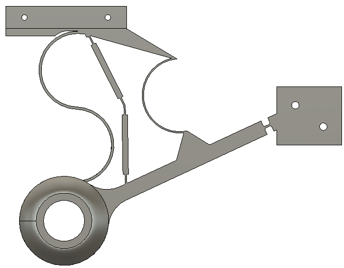
After virtual testing of the module, It was found that the rear suspension module performed well in terms of spring stiffness and strain energy but lacked fatigue strength as the possibility of the extended wheel travel increased substantially generating extremely high stresses in the hinge and the curved spring. There was a need of a mechanism which would avoid extended suspension travel and at the same time was able dampen the shocks from extremely uneven surface. In order to deal with this problem, a flexure hinge based compliant scissor mechanism was designed. This design decision also allowed to distribute load by adding yet another spring totalling the spring count to 4. When the wheel overtravel, while the wheel deals with extremely uneven surfaces, the fourth spring and the scissor mechanism are placed in the way that the fourth spring acts as an obstruction to now moving free end of the scissor mechanism thus transferring vertical bump loads into the fourth spring. As the wheel travels upwards the 4ths spring becomes stiffer thus producing a phenomenon of progressive spring rate wherein the stiffness increases exponentially with the vertical wheel travel as per spring designers will. In order to implement the mechanism design, a rear suspension kinematic design geometry sketch was made in Autodesk Fusion 360 as shown in the figure below
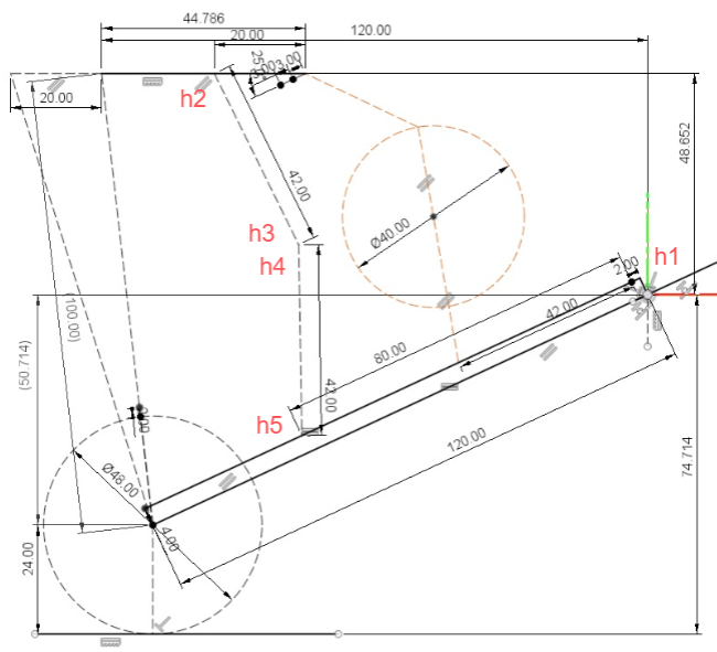
As shown in above figure, a total of 5 hinges were designed using “Detasflex” for which kinematic position analysis was performed in Autodesk fusion 360 to tune the mechanism for required motion and find angular displacement of the flexure hinge for its synthesis. Table below shows the angular displacement of respective flexure hinges.
Hinge | Angular deflection in degrees |
1 | 5.2 |
2 | 12.2 |
3 | 10.3 |
4 | 18.3 |
5 | 16.4 |
Table: Hinge angle deflection
Further similar process is followed to evaluate the stiffness of the mechanism by defining the deflection angle in ‘DetasFLEX’. As each hinge deflects at a different angle and has variable link lengths, values obtained from each hinge were processed separately. Table @ shows values obtained from flexure hinge synthesis.
hinge no | def degree | Software input link mm | original link length mm | force on hinge w/o compensation N | force on hinge w/ compensation N | force on hinge w/ compensation G | hinge stiffness G/MM |
1 | 5.2 | 40 | 120 | 1.034 | 0.345 | 35.146 | 3.515 |
2 | 12.2 | 15 | 44.487 | 1.787 | 0.603 | 61.441 | 6.144 |
3 | 10.3 | 15 | 44.487 | 1.49 | 0.502 | 51.229 | 5.123 |
4 | 18.3 | 15 | 36.204 | 2.735 | 1.133 | 115.549 | 11.555 |
5 | 16.4 | 15 | 36.204 | 2.44 | 1.011 | 103.085 | 10.309 |
Table: Hinge stiffness calculations
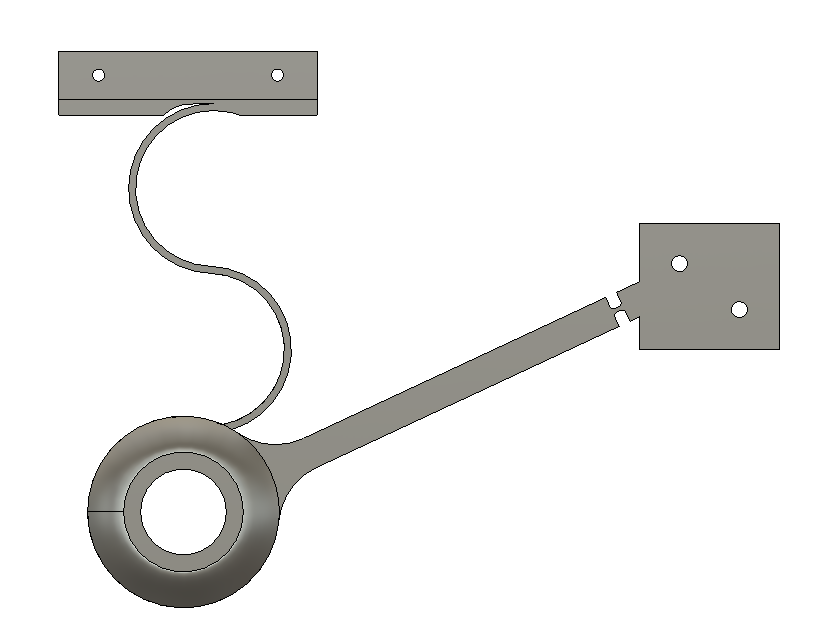
For the rear suspension module after considering the ride rate and motion ratio the spring stiffness was calculated as 0.50N/mm which was further divided by 4 to calculate the thickness of the spring. Similar to previous iteration using trial and error method, thickness of the spring is calculated. Final cad design in the image below
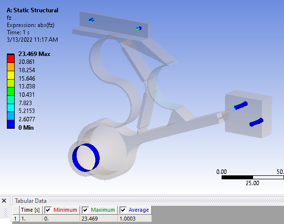
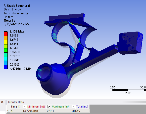
Furthermore, virtual validation tests were performed for the front and rear suspension modules using ANSYS workbench and results for the same are displayed below.
Fatigue test:-
In order to improve the reliability of the mechanism, it is necessary to find the safe service span of the mechanism. The fatigue strength of flexural hinges and compliant spring can be calculated. Using a stress-life approach wherein factors like stress concentration, notch sensitivity, surface finish, etc. are considered. Furthermore, FEA for fatigue failure of the mechanism would be done wherein a load or displacement of certain magnitude can be applied on the mechanism in order determine number of loading cycles which the module can withstand similar to mainstream automotive fatigue tests. Figure below shows test specimen used in fatigue testing.
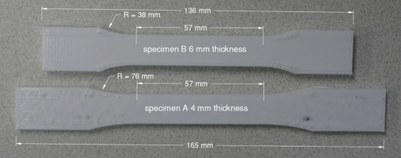
For an accurate fatigue analysis, proper test data of test samples under fatigue loading is required. For this fatigue testing was conducted on an MTS 858 load frame with a 25 kN load cell in accordance with ASTM D7791—standard test method for uniaxial fatigue properties of plastics. Specimen were subjected to a sinusoidal waveform loading of stress ratio R = 0.1 at 1 Hz up to 10,000 cycles and then 2 Hz until fracture. A total of 16 specimens were tested for 90, 80, 70 and 60% of UTS. S–N curves shown in Fig. @ were created using stress levels from testing of specimens.
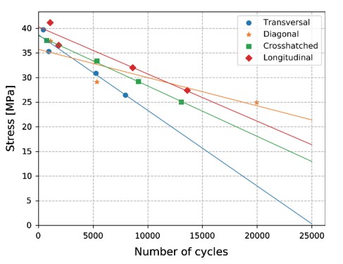
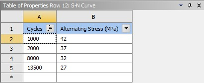
Required data was extracted from the S-N curve and was fed into ANSYS engineering data material properties as shown in figure below.
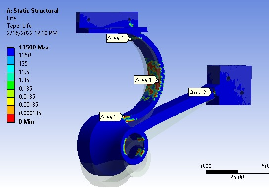
Furthermore, load vectors in the form of displacement were applied on the free ends of the suspension module simulating wheel travel. After solving the domain, possible areas of failures were identified as shown in figure below.
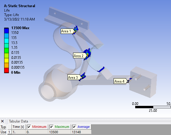
| No. of Probes | Average Life (Cycles) |
Area 1 | 31 | 5365.24 |
Area 2 | 19 | 5115.2 |
Area 3 | 24 | 2634.23 |
Area 4 | 15 | 9790.16 |
Table: Normalised fatigue life values per area
Later on, in order to analyze least fatigue life of the suspension module, fatigue life at each node was extracted in groups from the places of high failure probability. Average of each group was taken in order to deduce the least fatigue life of the module. Table above shows fatigue life at each possible failure area which shows that the area 3 has the most probability of failure with service life of 2634 cycles.
Additive manufacturing of suspension module:-
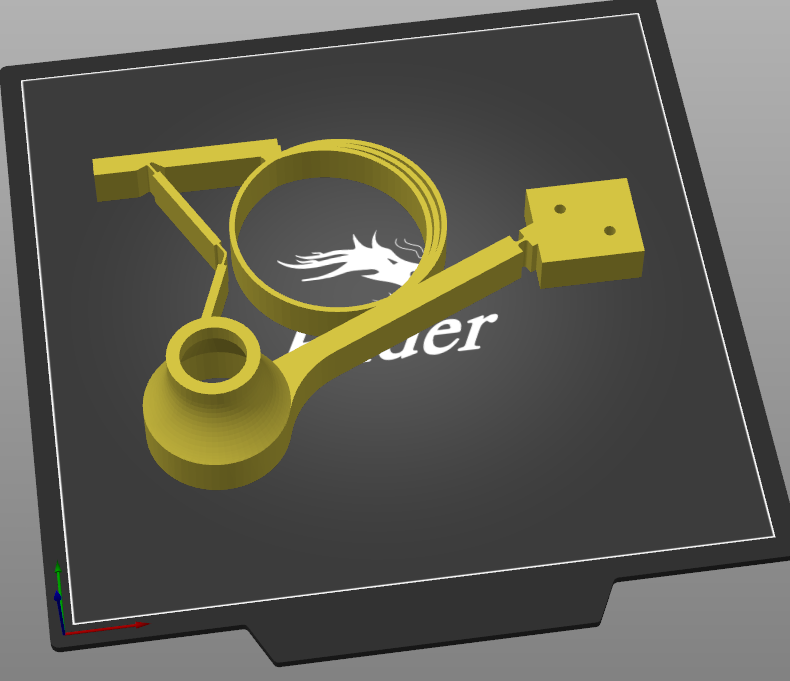
For additive manufacturing of the subsystem, FDM (Fused Deposition Modelling) is used. The 3d printer which will be used for the manufacturing Process is Creality Ender 3 which has a printing volume of 210x210x230 mm. PETG (Polyethylene Terephthalate Glycol) which is used as printing material for the module because of its good elastic properties, and good printability. Print layer height is set at 0.1 mm to improve Inter-layer adhesion. 20 Due to the anisotropic nature of 3D printed objects, special attention was given while designing and slicing of the part.
3d models were exported from Autodesk fusion 360 to Prusaslicer in STL format. Figure below shows a 3D model of rear suspension module imported in the software.
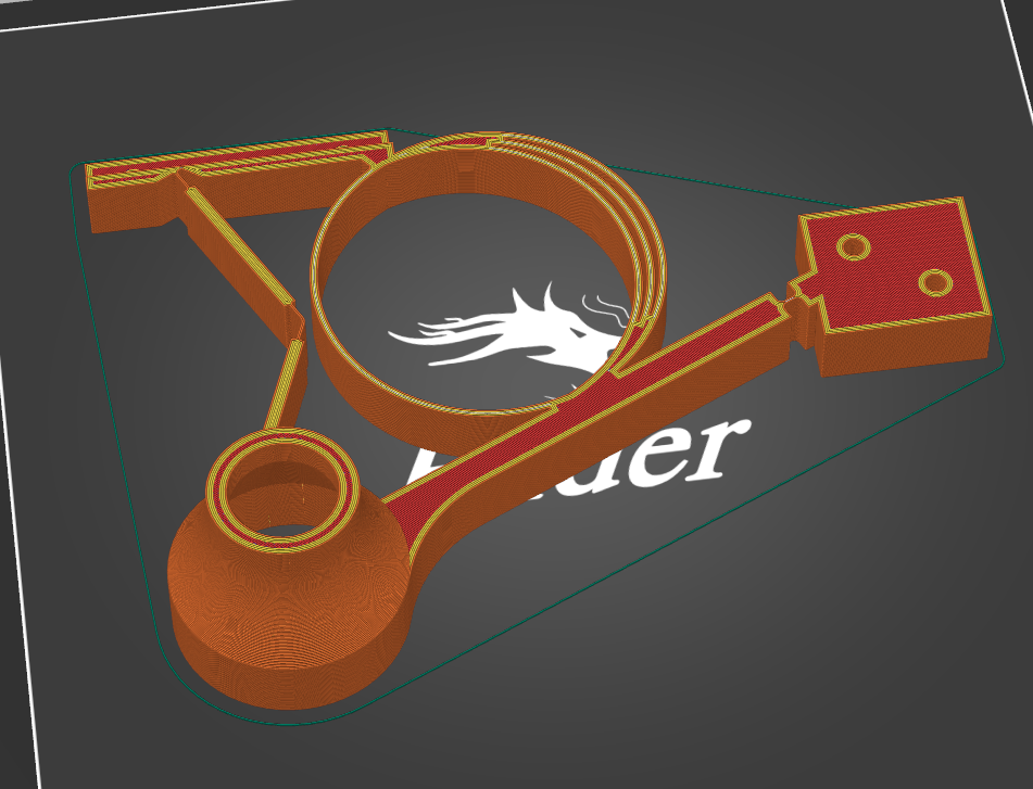
Furthermore, in order to increase strength of the module and reduce its printing time following parameters were selected for slicing,
Parameter | Value |
Layer height | 3.0mm |
Infill | 20%(Grid) |
Horizontal walls | 6 layers |
Supports | Touching build plate |
Speed | 60mm/sec |
Table: Print parameters
Result and Discussion
Deflection test
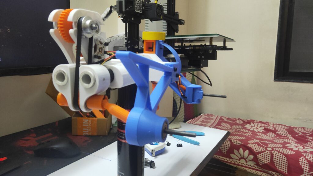
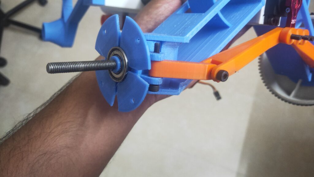
Purpose of this test is to determine the vertical deflection of the test rig body to determine its ride rate (ride stiffness) and to compare it with the initial design values and to find the range of error throughout all iterations. Figure below shows the test setup for the same.
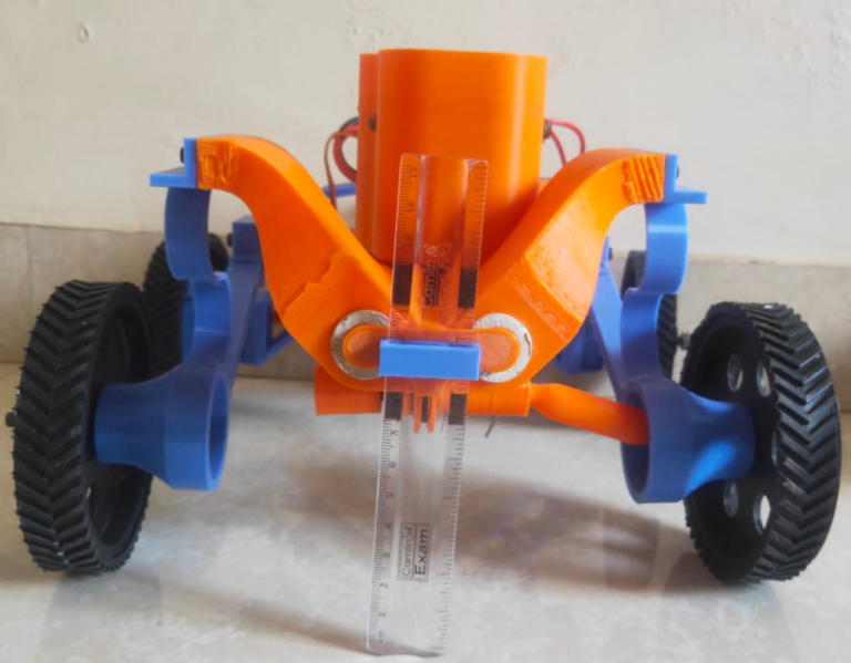
As shown in the above figure a vertical measuring scale is mounted on the test rig which touches the ground and slides over the scale mount whenever there is a suspension deflection. Initially the test rig is suspended above the ground in a way that the wheels barely touch the ground. As the measuring scale is grounded, initial height readings are recorded.
Later, the test rig is made to rest on the ground in a way that the suspension modules are loaded causing the main body of the test rig to sag. This deflection in height recorded using measuring scale and the value is subtracted from initial height. Results for all iterations are displayed in the table below.
Iteration No | Initial value | Value after deflection | Actual deflection | Theoretical deflection | Error% |
1 | 44 | 45 | 1 | 2mm | -50 |
2 | 45 | 48 | 3 | 3mm | 0 |
3 | 45 | 48.5 | 3.5 | 4mm | -33 |
4 | 45 | 46.5 | 5.5 | 6mm | -9 |
Table: Deflection test results
Results indicate that due to strain energy buildup, iteration 1 and 3 showed 30-50% less deflection than theoretical deflection while iteration 2 and 4 with dual semicircular spring in series formation showed almost perfect deflection when compared to theoretical deflection.
Bump interaction test
Purpose of this test is to determine the shock absorbing capacity of the front and rear modules over the bump. Figure shows the test setup for the same.
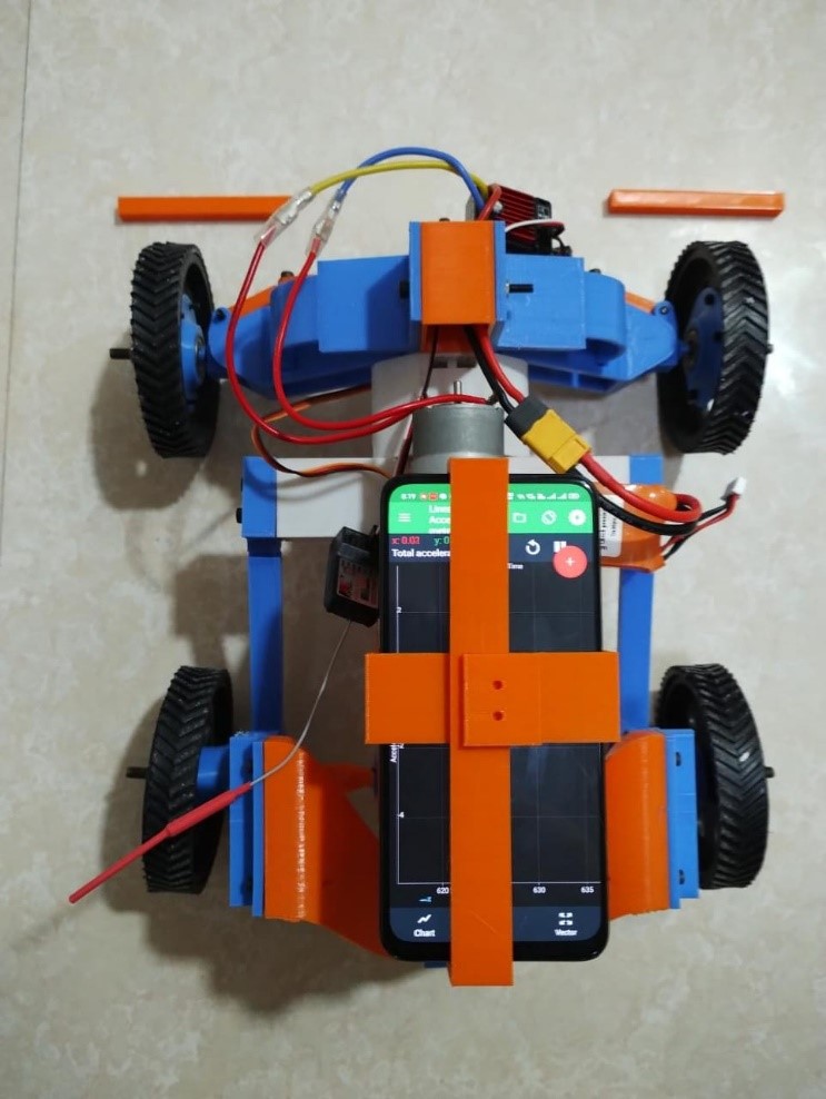
The test rig is tested on a single bump of 10mm height. As the test rig interacts with the bump at the speed of 5.2 MS, upsprung weight of the suspension module accelerates and generates a force and the part of that force is absorbed by the curved spring and remaining force is transmitted to the main test rig body where the effective acceleration data is recorded and later compared with the with the rigid suspension module to evaluate the damping performance. Table below shows the resultant acceleration values of respective suspension module iterations.
Iteration number | Max resultant vertical Acceleration m/s^2 | % Acceleration of rigid module. |
Rigid | 53.02 |
|
1 | 35.63 | 70 |
2 | 29.49 | 58 |
3 | 26.80 | 52 |
4 | 24.30 | 50 |
Table: Vertical linear acceleration values
As each new iteration has been designed to deliver better performance than its previous one, when compared to the rigid suspension module, it was found that the suspension module performed 30-50% better throughout all iterations.
Conclusion
Design, analysis and additive manufacturing of a print in place suspension system using compliant mechanisms was performed successfully wherein a test rig was designed and fabricated to test the manufactured suspension module. The prime objective of the project was to develop a design methodology for the synthesis of the print in place suspension system using compliant mechanisms which were achieved using non-linear FEA and castigalino’s theory for curved beams. Furthermore, the designed mechanism was be optimized for fatigue failure throughout the iterations and then 3d printed using the FDM method. Finally, the design validated was done using deflection and bump interaction test. Thus, by validating the design, this project will achieve its objectives so to fulfil its purpose of
- 3D Printing suspension system on Mars.
- Reduction of spacecraft payload weight
- Reducing fuel and logistics cost of space travel missions.
Future scope
- Suspension modules can be redesigned using other hinge types to further performance optimization.
- Materials with better admissible elastic strain percentage can be researched upon.
- Use of SMM (shape memory materials) or materials which can change its physical shape upon external stimulation e.g., Force, heat, electric current, etc. can be explored.
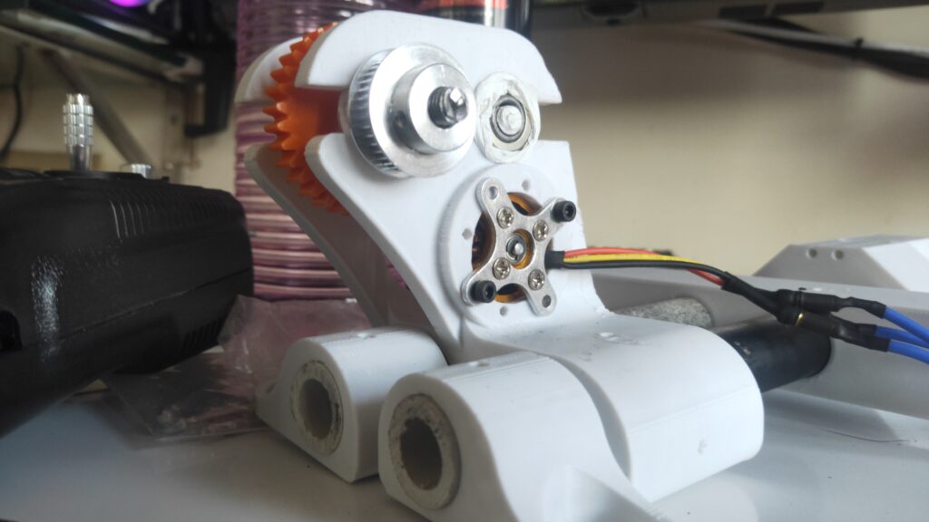
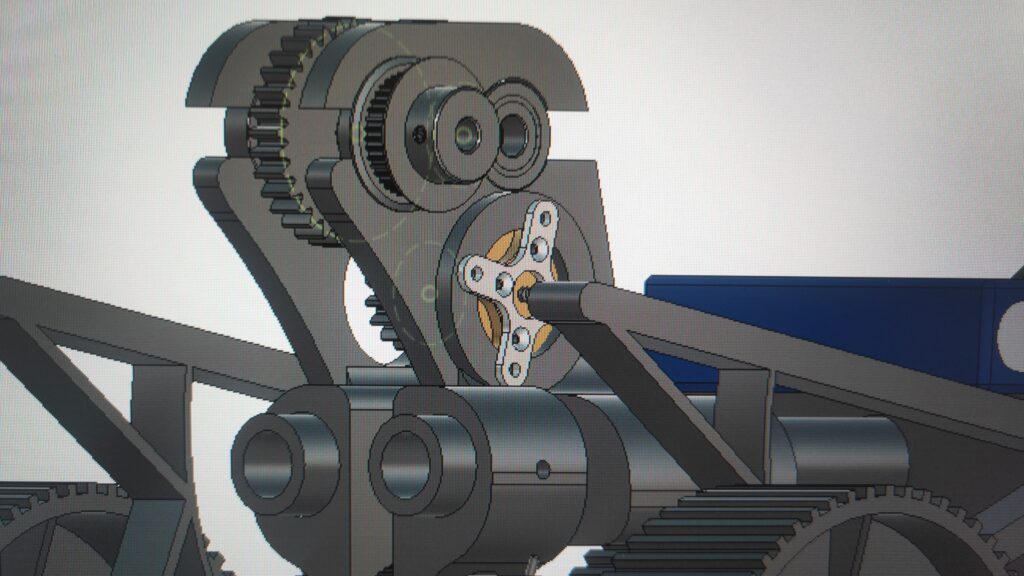
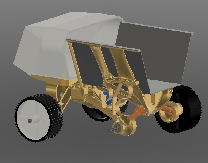
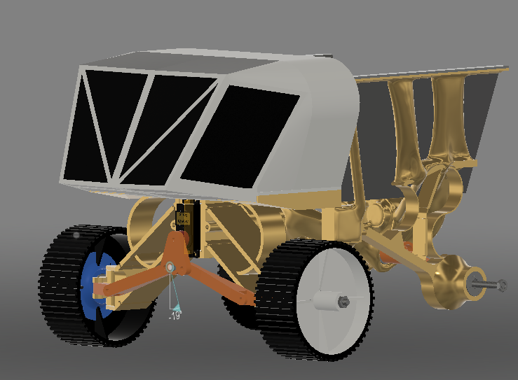
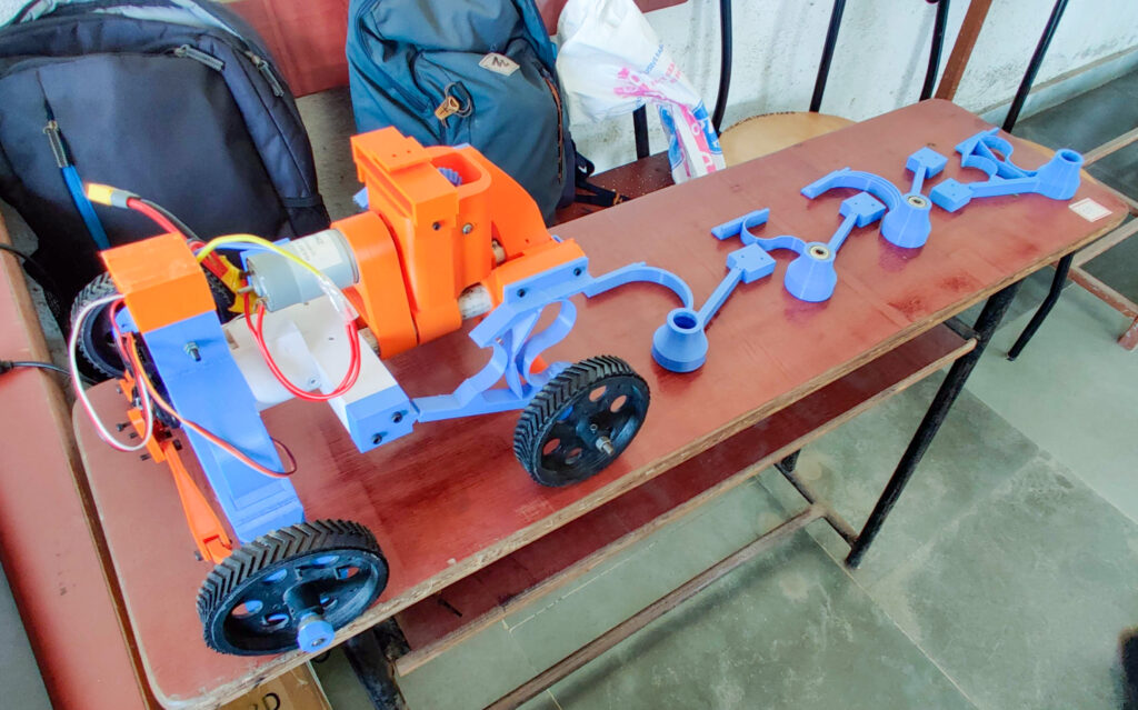
Working model and and project images