SAE BAJA suspension steering and brakes
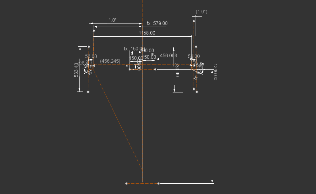
Suspension system design
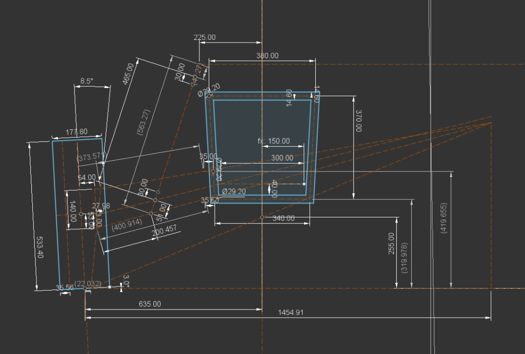
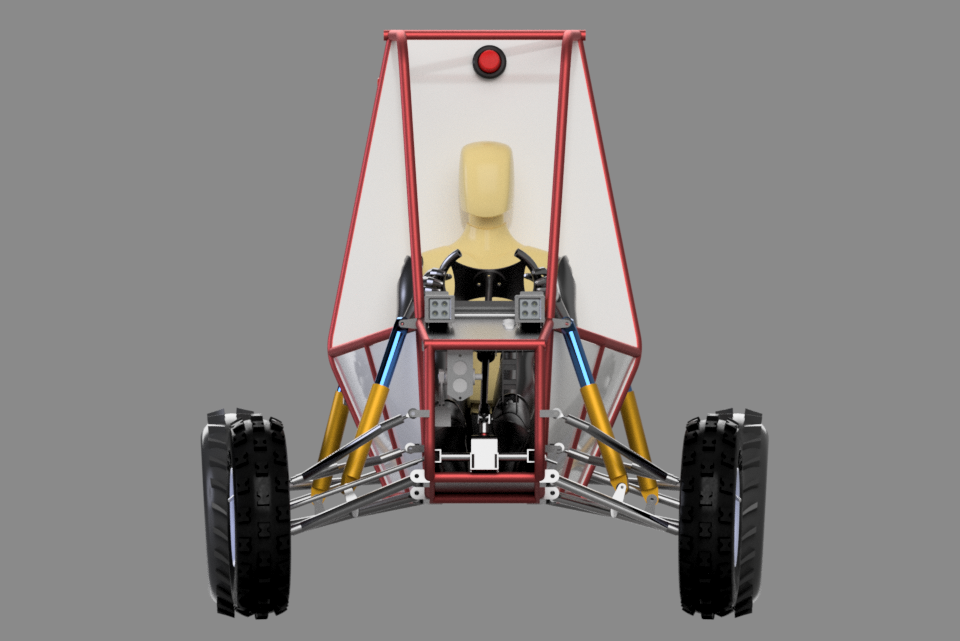
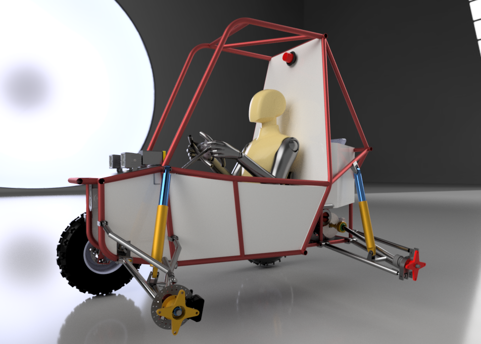
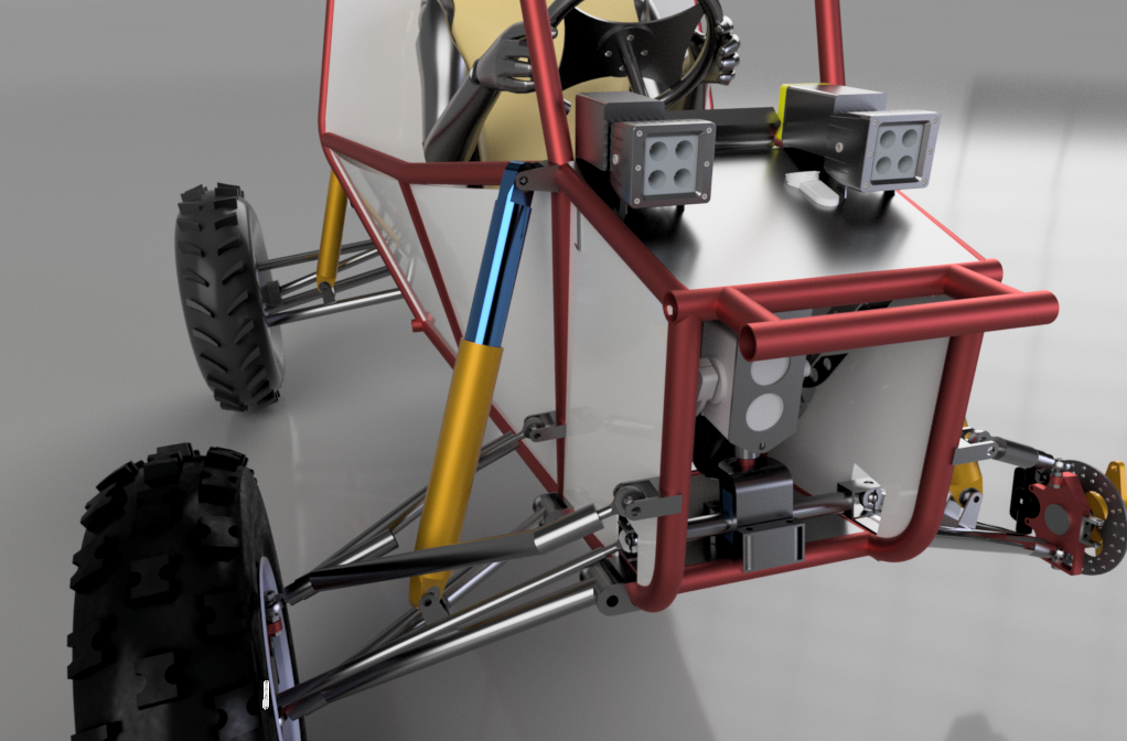
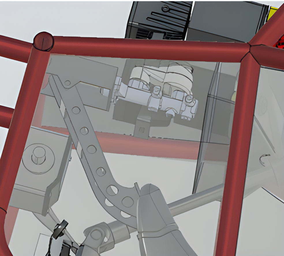
After 2 years of learning vehicle dynamics from the internet and hundreds of research papers, this was the best iteration we developed so far. Our main goal was to design a compact vehicle with a centre of gravity close to the ground. So to achieve our goals, we had to work on our vehicle component and subsystem packaging. Upon finalising basic suspension parameters, suspension geometry was made to determine skeletal dimensions for uprights, and wishbones, followed by wheel packaging design. Finally, hardpoints were extracted from the geometry sketch to perform kinematic analysis of the suspension system. Fox 19.2 inches dampers were incorporated in the system to absorb shocks from the wheel-ground interaction. All components were validated for a 6 feet fall case with safety factor of 3.5.
Steering system design
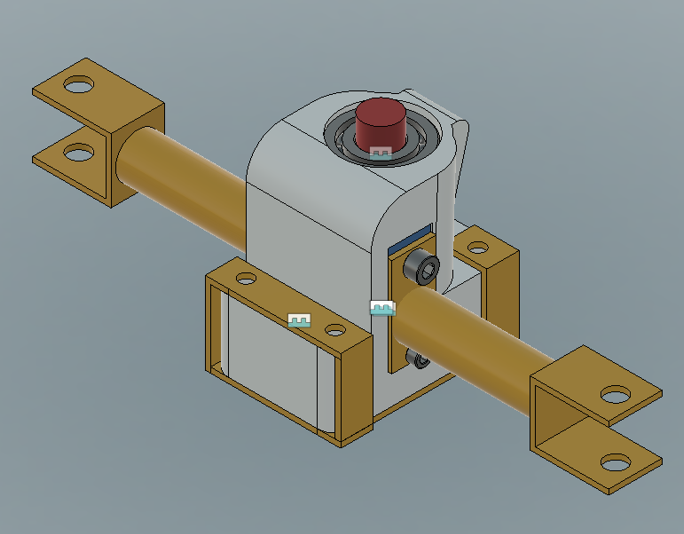
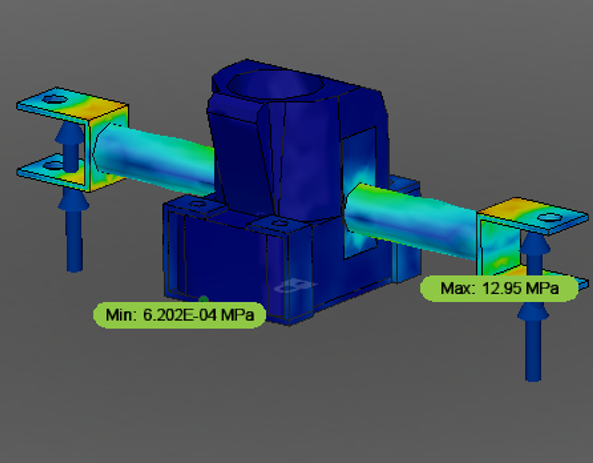
Rack and pinion was designed which travels from one end to the other end (52 mm) in 1 turn of the pinion. The steering ratio of 2.9:1 is achieved which means for every 2.9-degree rotation of the steering wheel tire will be turned by 1 degree. A 3D-Printed rack casing was designed for the system. Steering is a crucial subsystem wherein multidirectional forces act on the subsystem while in dynamic conditions. In order to validate the design, multiple loads were hand calculated for various loading conditions. FEA results can be seen in the image above.
Braking system design
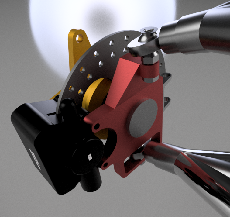
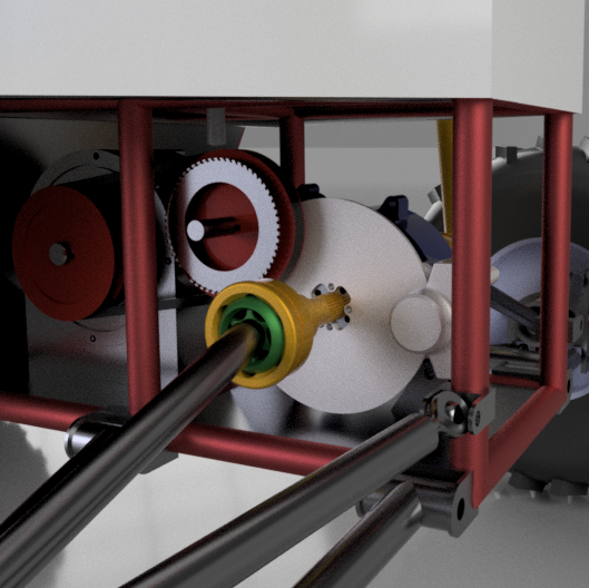
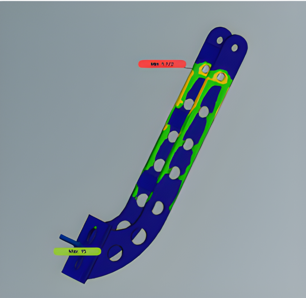
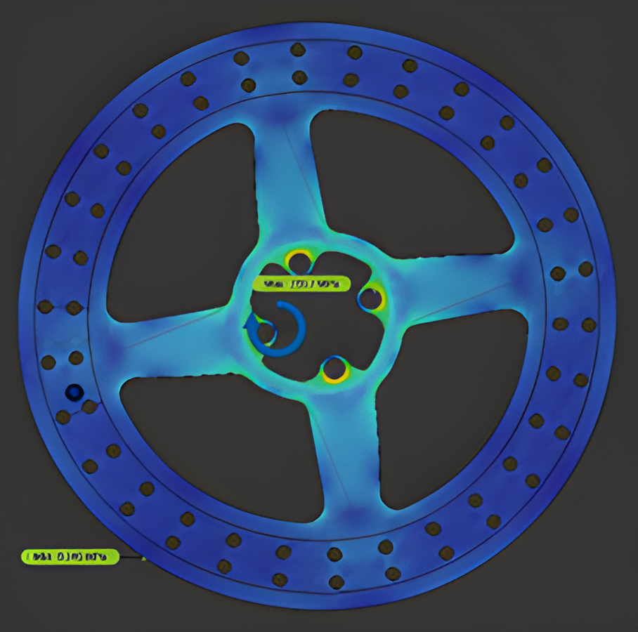
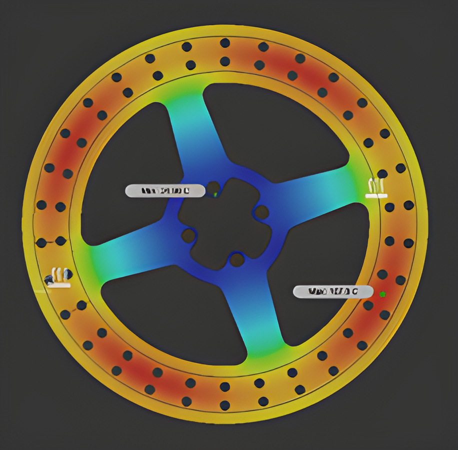
The purpose of the braking system is to increase the safety and manoeuvrability of the vehicle by statically and dynamically locking all four tires on both paved and unpaved surfaces. The material selected for the brake disc is 4130 steel considering its weight and availability. A laden load of 250Kg was considered while designing the braking system. The brake circuit used is of the horizontal split type with an inboard type rear brake calliper and rotor. Furthermore, it is controlled by a single pedal in line with a single master cylinder. Bosch tandem master cylinder is used which has a bore diameter of 19.05mm. The material used for the brake pedal is AISI 316L with a pedal ratio of 7:1. Armoured steel braided brake lines run through the length of the car and flexible rubber lines at the A-arms in the rear for suspension travel. These were chosen due to their flexibility and their strength and ability to maintain high line pressure values. Vespa floating callipers from KBX-OEM and Pulsar 220 fixed calliper were chosen for the front and rear brakes respectively. Analysis of the brake system was performed on the vehicle with a velocity of 40 KMPH. For an input force of 300N on the pedal, the resulting deceleration was around 0.68 g. At this deceleration, it would take the car around 2.50 s to stop. Results can be seen in the above images. A safety factor of 4 and a temperature of 130-degree Celcius were maintained.